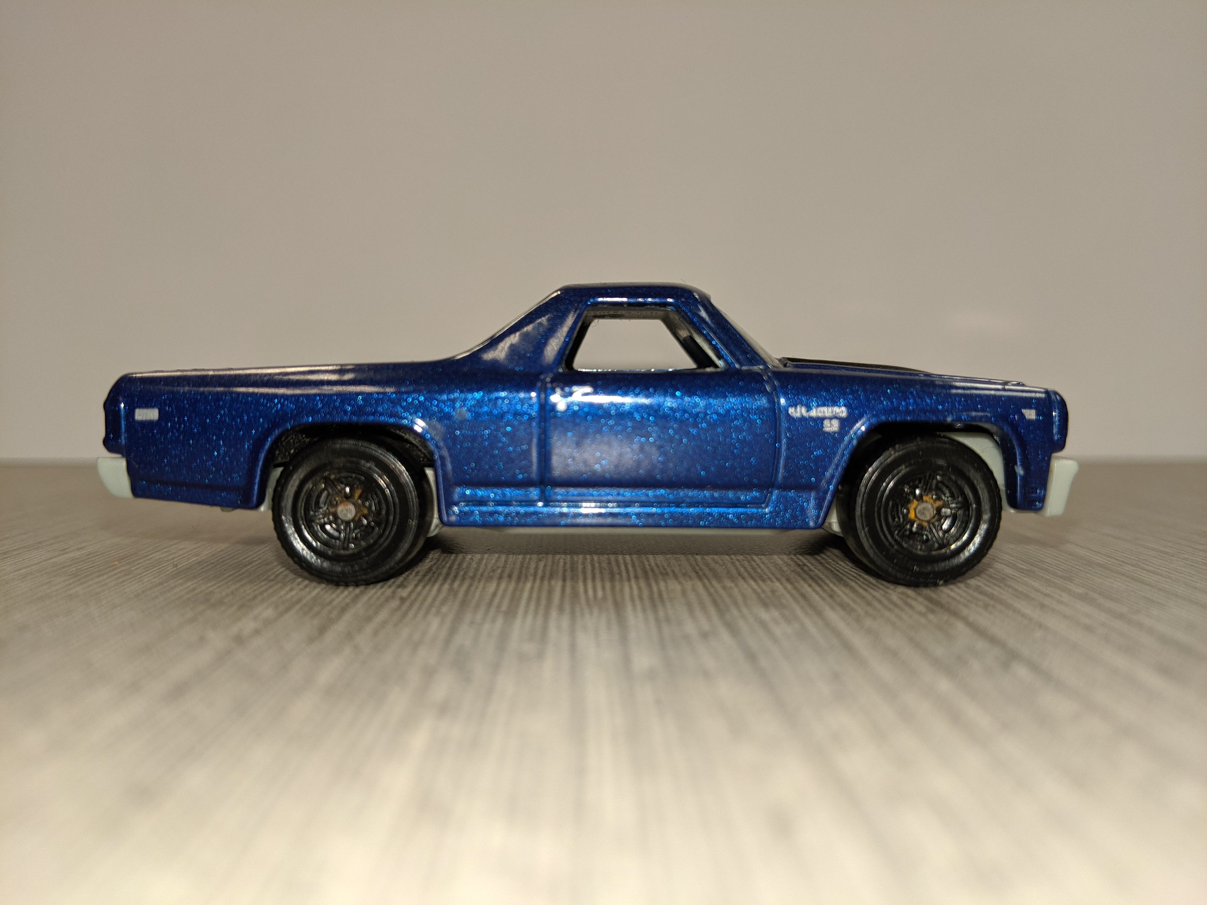
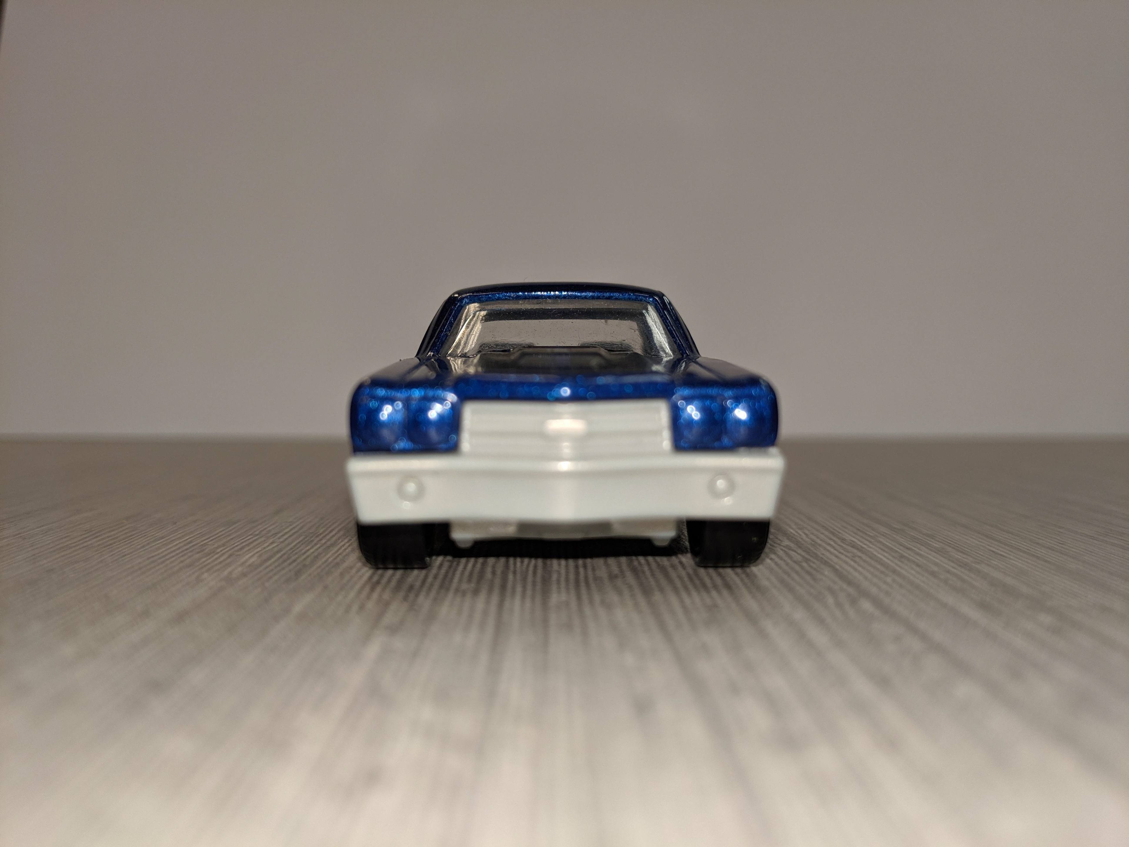
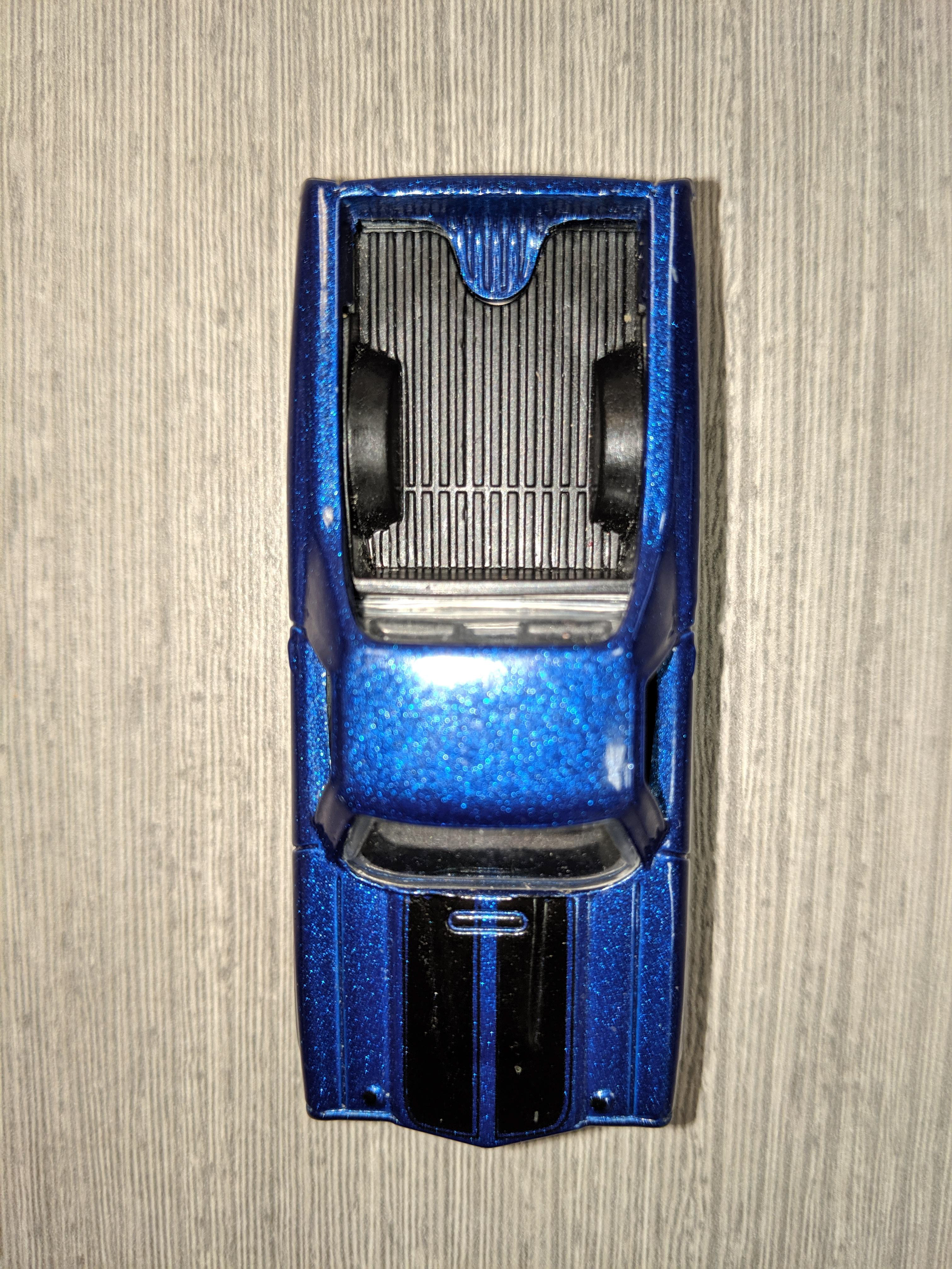
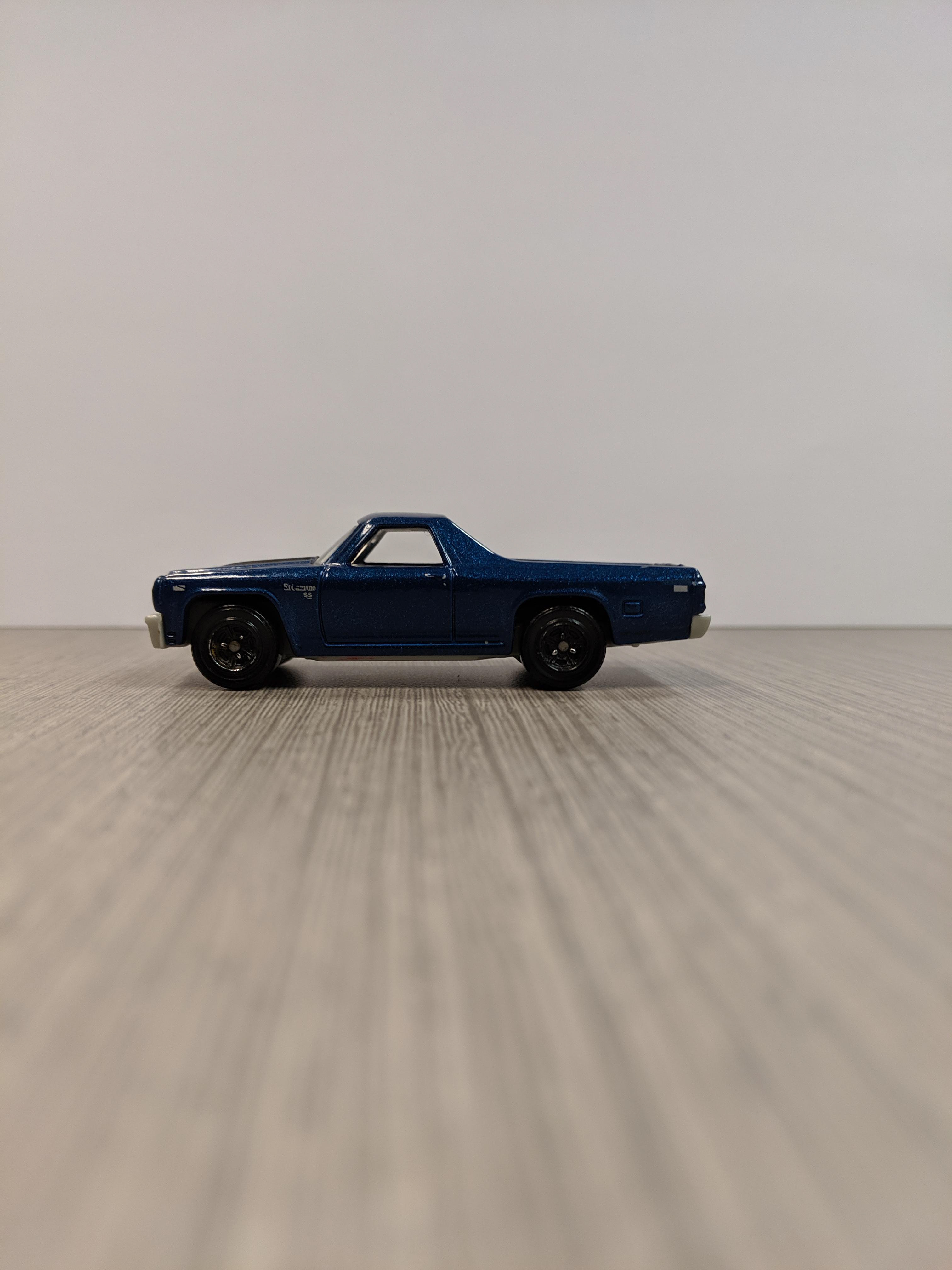
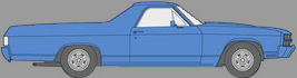
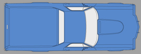
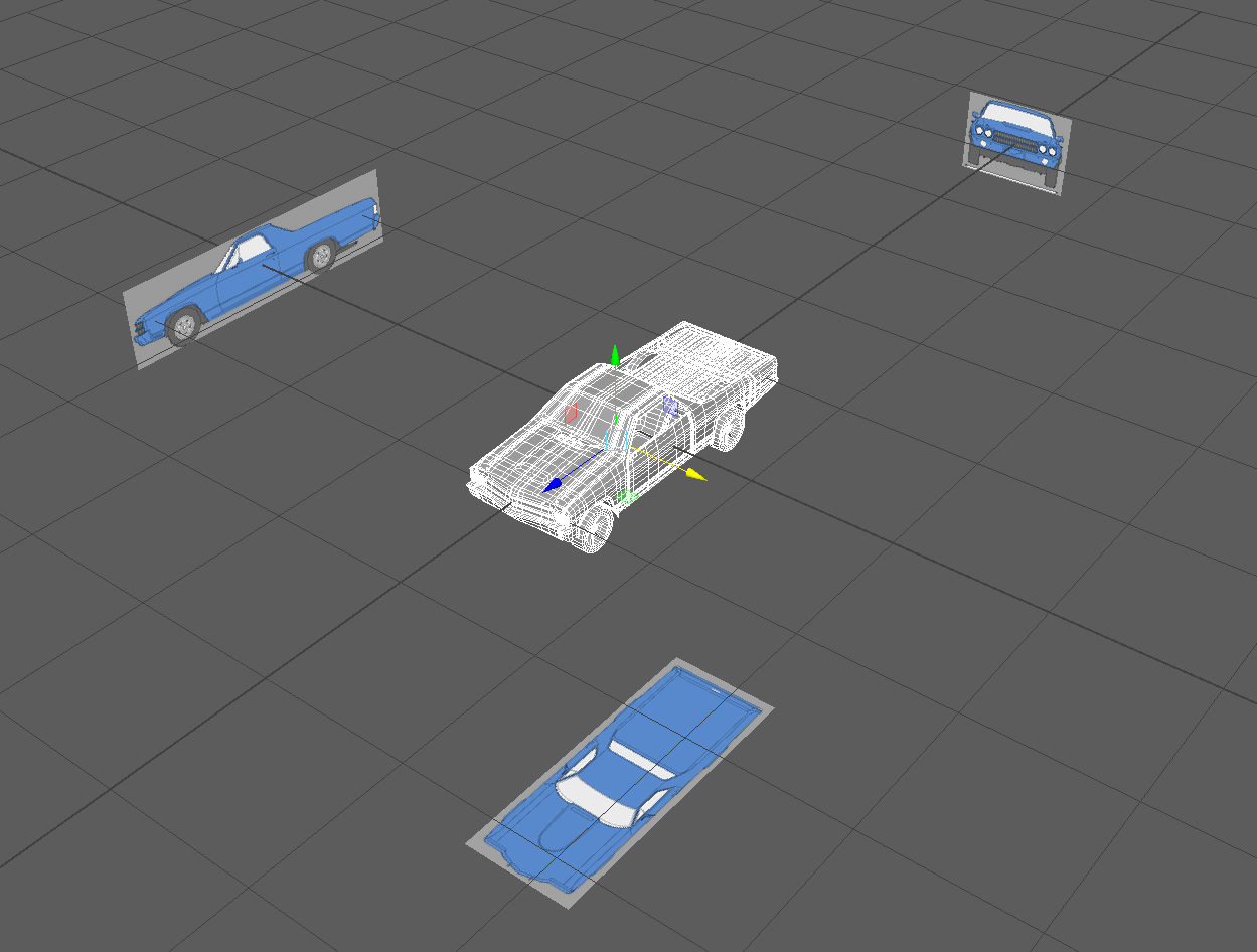
Pictures of the Reference Object Car are provided Below


Solution:
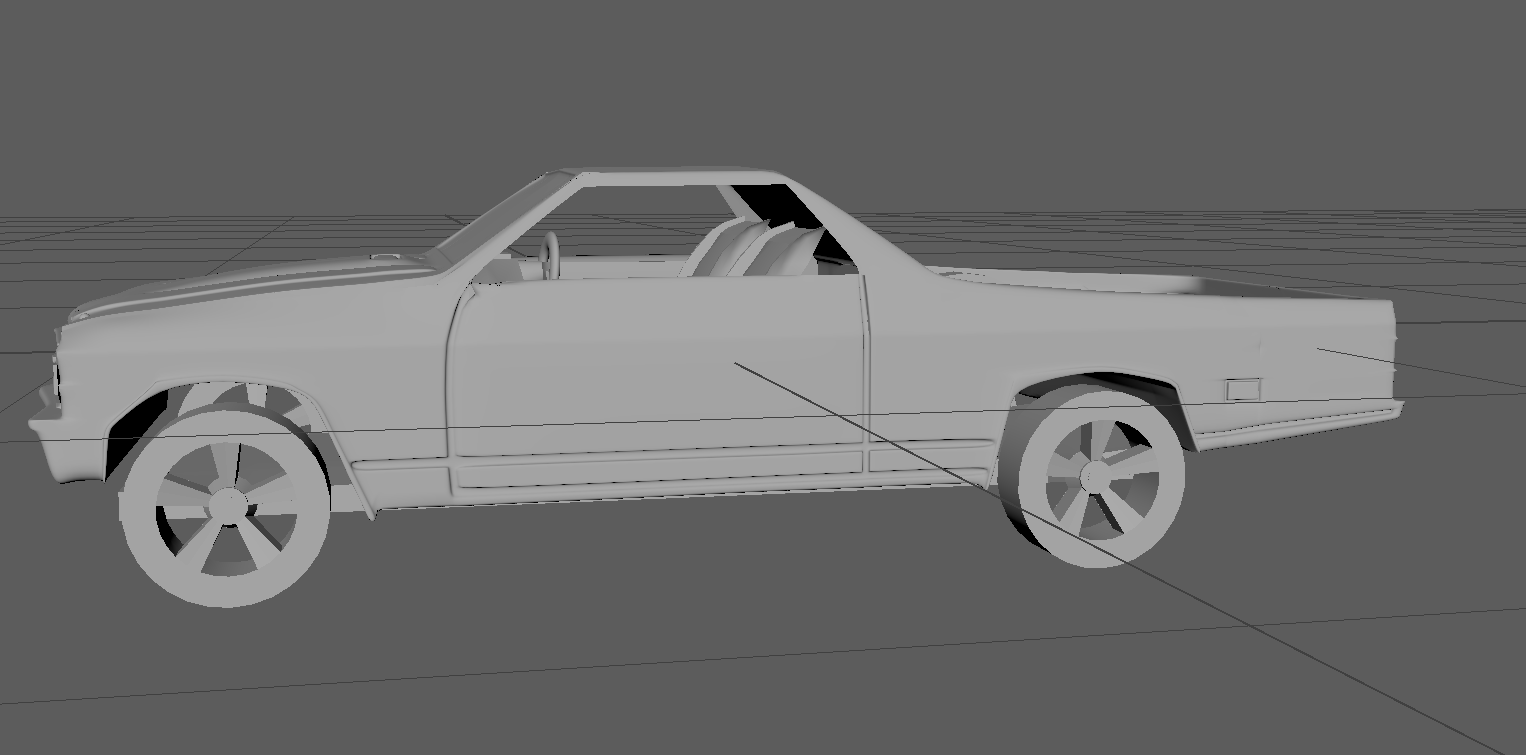
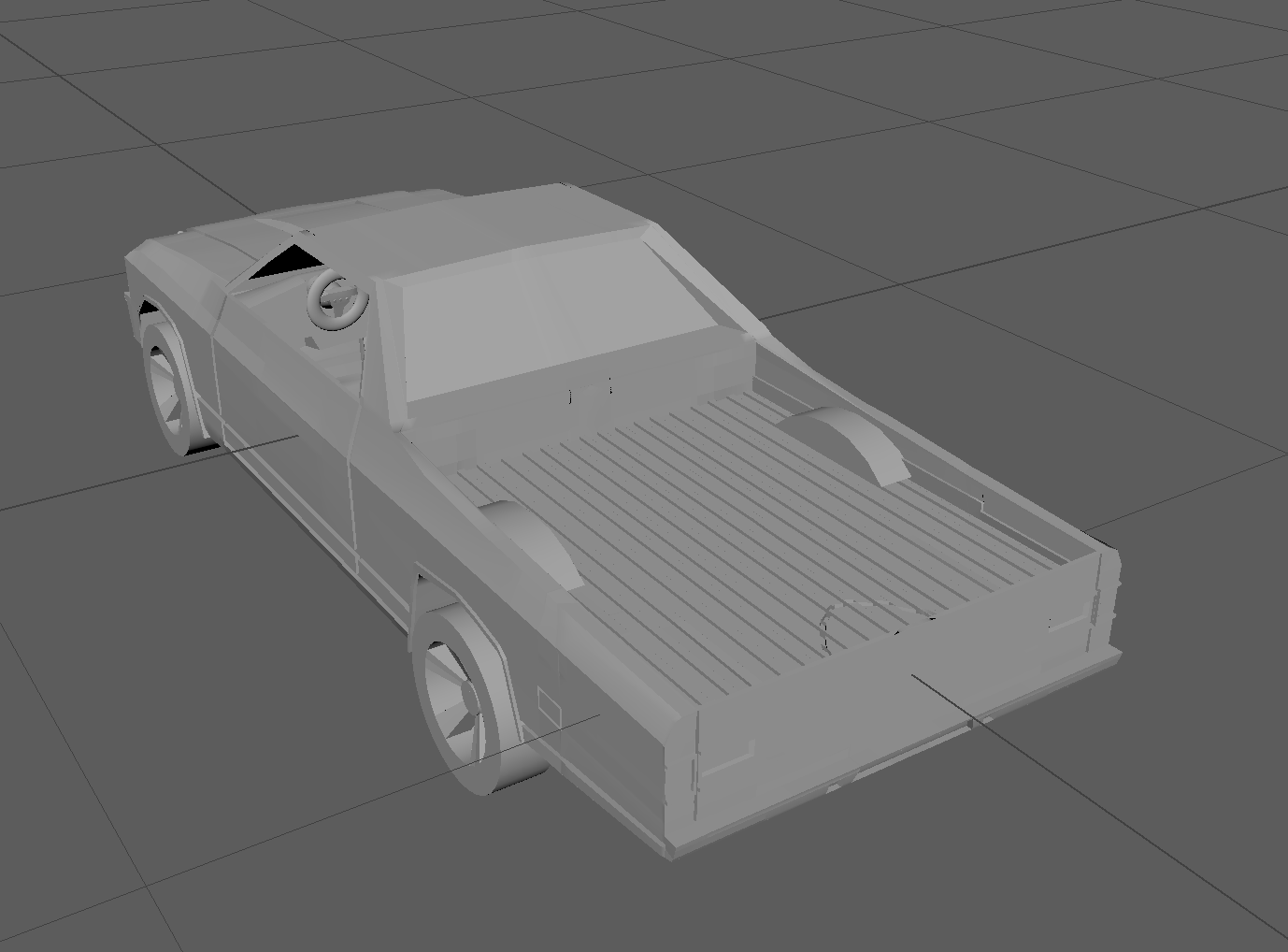
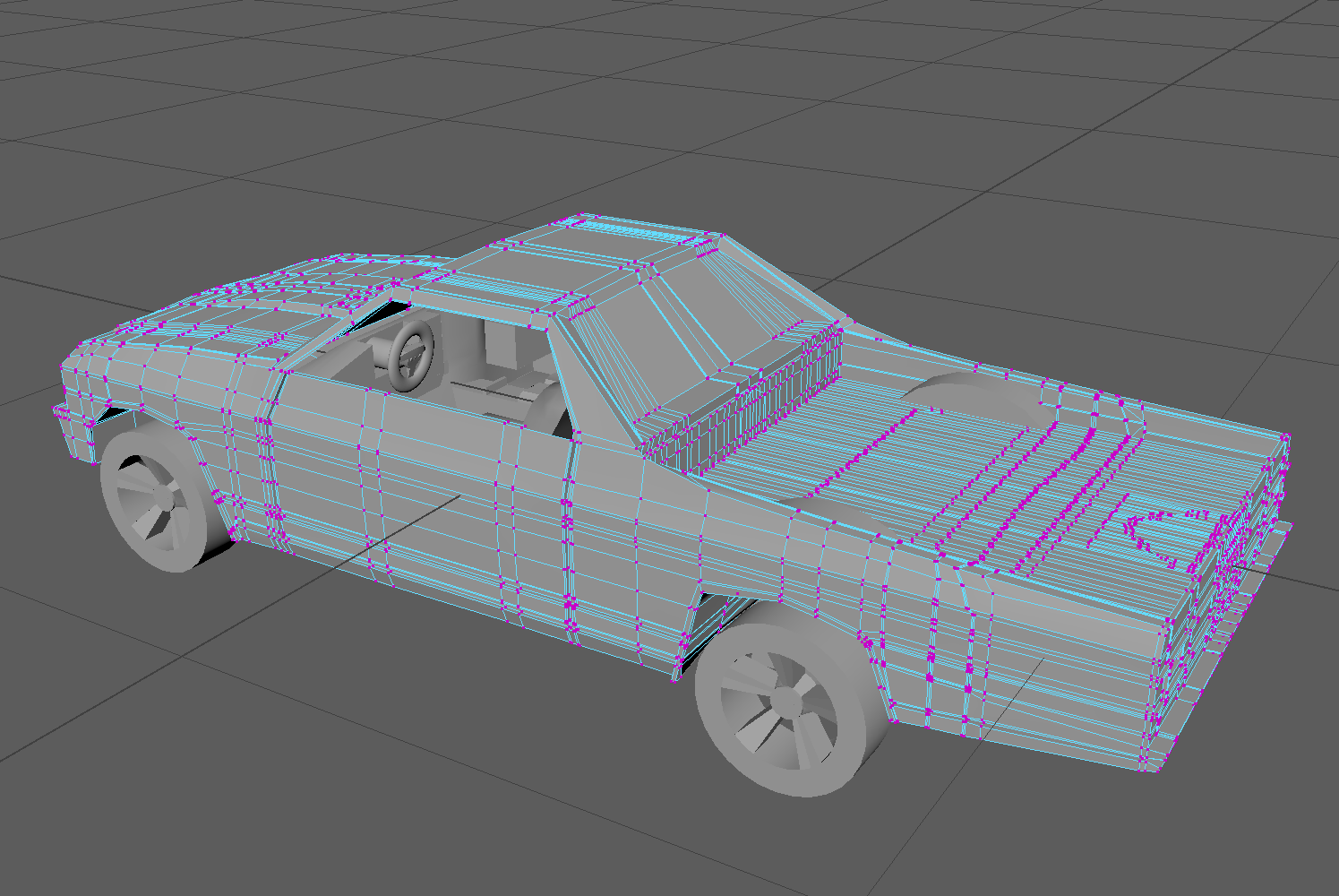
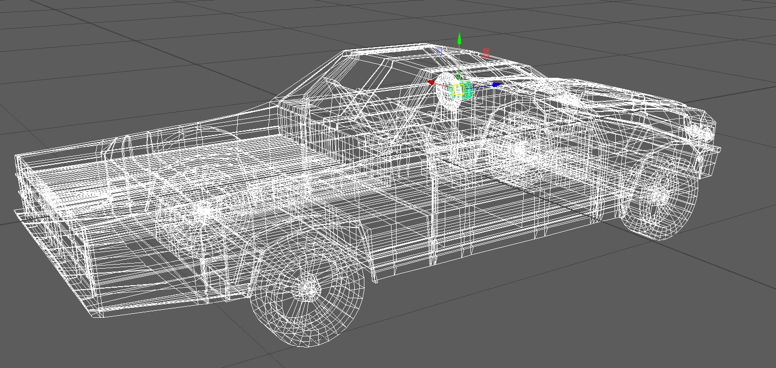
To model the given Chevrolet '79 El Camino Car, I needed to understand the geometry of the car to a somewhat detailed degree to understand where and how to begin. I found this car extremely difficult to model as the profile, shape of the car isn’t as easily perceivable as other objects with just vision, coupled with the fact that curvature associated with vehicles definitely complicates the geometry and my understanding of it. To build the car in Maya, I broke down the main process into 4 phases. The first phase involved understanding the geometry and the model of the car. The second stage dealt with creating a basic rough shape of the of body of the car as one single unit using. This phase involved using polygons and further, a box modeling approach to roughly match the shape of the car. In the third stage, the main focus was to add to the simplistic geometry making it look more like the car in itself. This phase is the most time consuming phase where the real meat of the car (the core shapes down to the t) gets defined and adjusted accordingly. In the final phase, attention was directed towards embellishing the finer details such as adding ridges, dents, headlights, etc. ; suffice to say that any secondary object such the interior of the car dashboard, steering wheels, seats, etc. were modeled to supplement the main car body. I explain in detail the process I took to model this car in Maya 2019. I used of process of symmetry to model the car. Essentially, I modeled one half of the car and created a symmetric duplicate in the end after which I combined them to form the entire car. I describe the steps I took in a somewhat specific order bearing in mind the general theme follows the order of the phases described above.
Setting Up Reference Images:
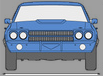
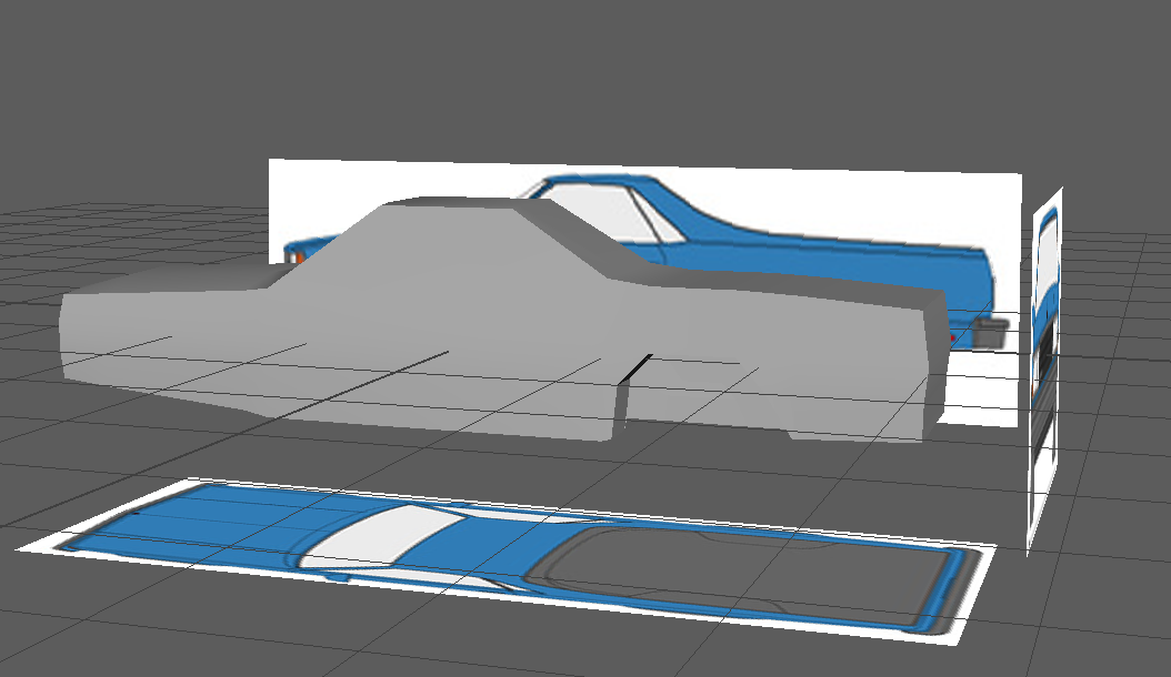
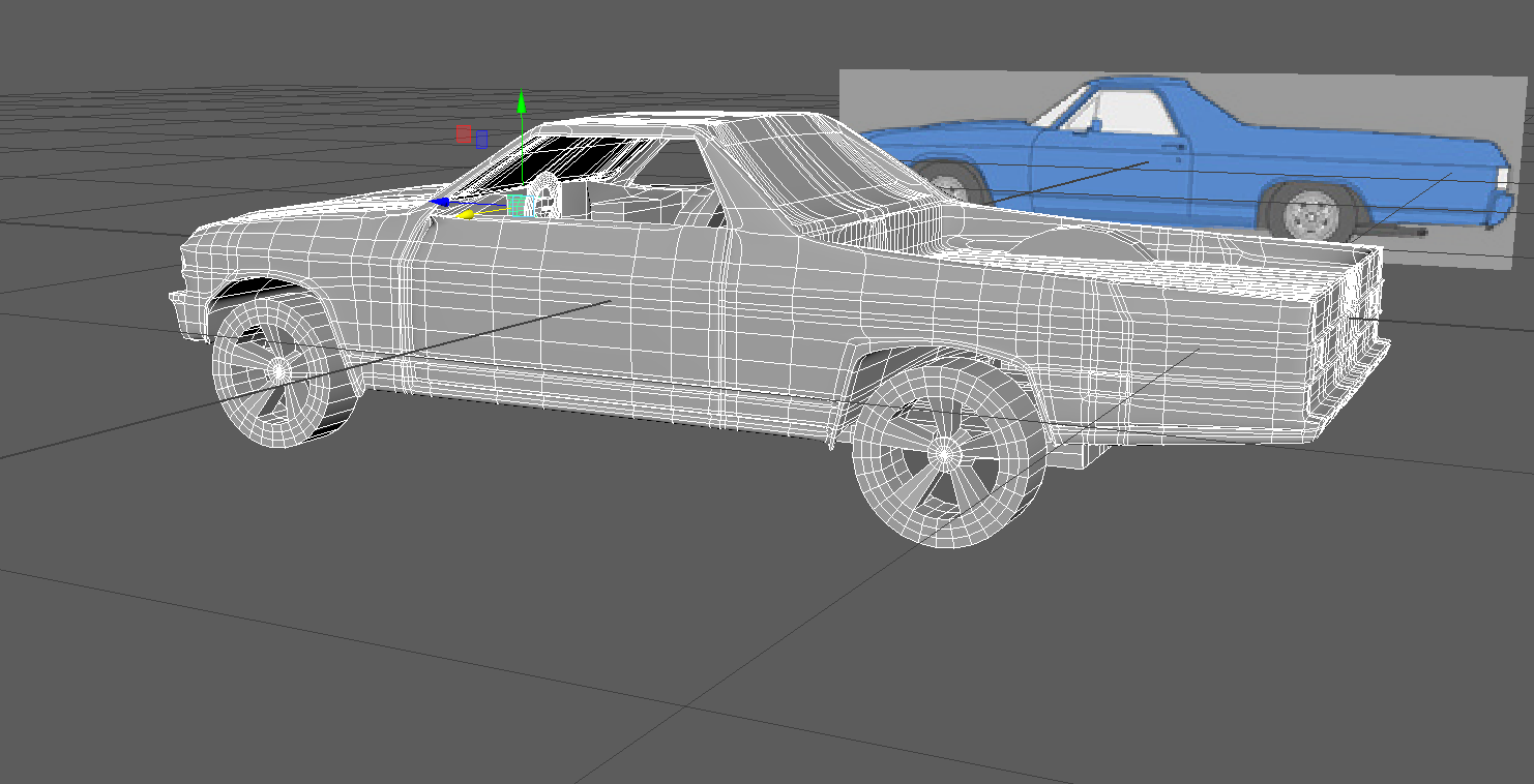
At first I spent a considerable amount of time vacillating between whether or not to use reference images of the car that I had taken with my phone(not taken with great expertise) or to find a more precise one of the blueprints online. I was able to find some reference images for the exact same car model (El Camino ‘79) online. But these reference images weren’t of the greatest clarity but I still decided to proceed with these since I trusted these more than my amateur photography skills especially when it is required to take photos with the same scale. However, I took a conscious decision to go with these images which looked had slight variations of the model car. I decided to adjust these variations later once the general model was built. I made use of the front view, top view and side view images of a ‘79 El Camino. I did make sure using Adobe Photoshop to see if the reference images indeed were indeed orthographically valid and to scale. I imported these images in to Maya, placed them at sufficient distances from each other to avoid congestion. Apart from the model of the toy car pictures above, I used reference images that I have provided below.
Defining the body of the car:
After carefully looking at the car and the reference images, I decided to begin with a cube as the basic shape. This was what I conceptualized as the basic shape of the body of the car.I scaled the cube’s width to 3 times in the x axis to match the length of the car dividing it into 6 parts on the length, having 3 subdivisions along the height and 4 along the breadth which corresponds to the front and the back of the car. I decided to box model with the intention of working on three different parts of the car, namely the front, the middle and the back. Bear in mind that I made use of sole object for the body of the car not using multiple objects for front, back and middle. While this would have made the modeling job easier, after doing some research and talking to some experienced modelers, I decided to do it the right way with just one object as the main body. I also used some opinions from online forums from modelers that use SolidWorks to model precise objects.
Adjusting the Object Model to match the shape of the car:
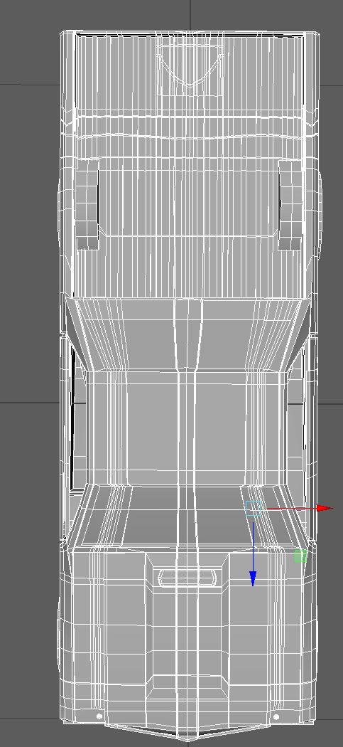
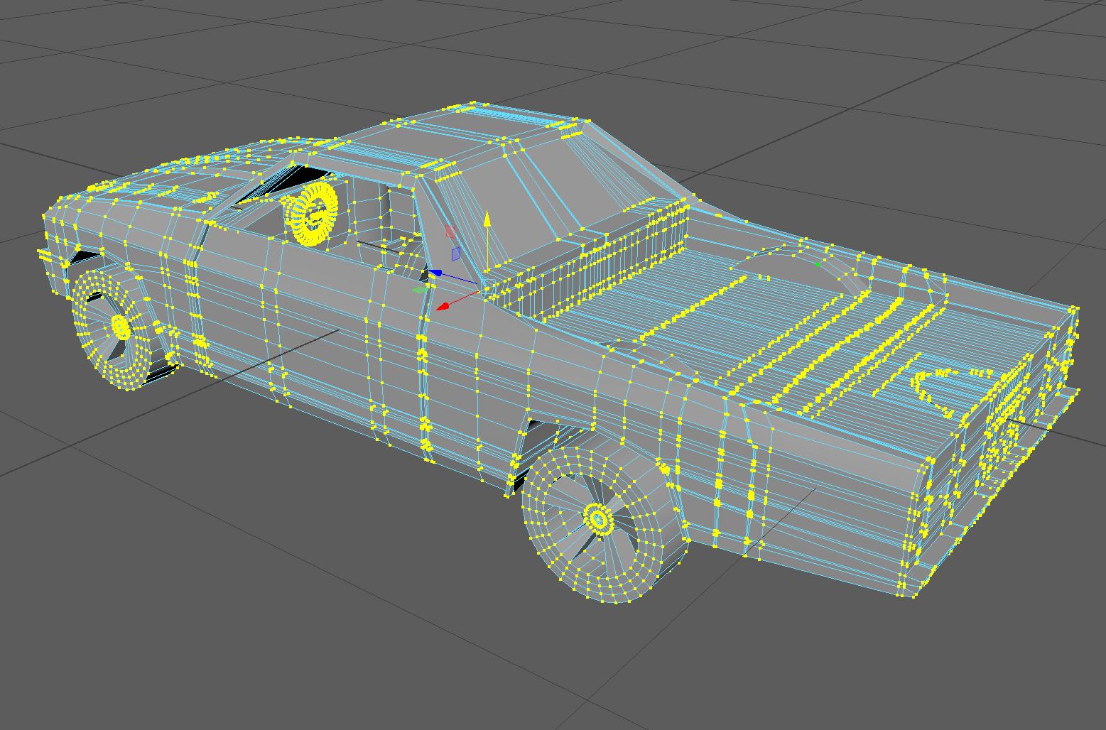
In this step, I simply moved around vertices in wireframe mode to match the shape of the car. This meant that I stared with one view, moved or rather translated the vertices to help match the profile of the car from that view. After finishing the translation of all the vertices in one view, I proceeded to do the same thing in another view and then the next with the same approach, This way I ensured consistency between views. While doing this from each view, I needed to every now and then add edge loops length, breadth and depth wise to account for the tapering, curving, sloping profile of this car. However, I added edge loops only when it was absolutely necessary to avoid creating extra faces and polygons. The basic outline of the car at one point during this process can be seen in the first few images. Bear in mind I modeled only the left half of the car, which meant that in the front and top view, I accounted for only one half the car-the left one.
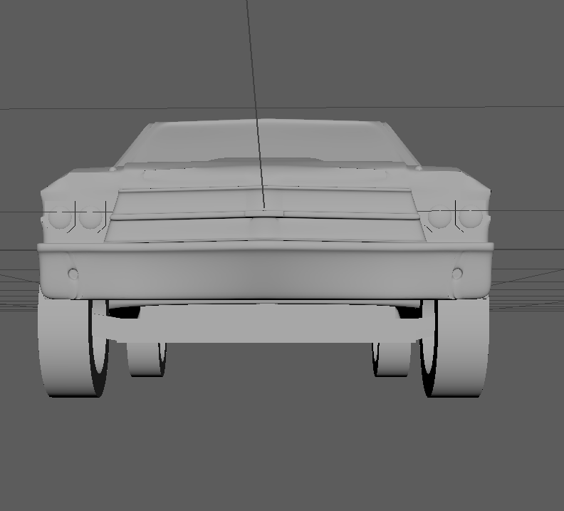
Modeling the front of the car:
To model the front of the car, after defining the profile, I first decided to model the grill of the vehicle which required an accurate understanding of the grill. This wasn’t easily visible in my reference pictures. So by touching and feeling the model’s grill, I extruded faces and scaled them accordingly to match the model. I also merged extra vertices that were formed as a result of extrusion. I also modeled the front scoop of the car which is located on the bonnet. While the slope of the scoop is not easily perceptible by using just vision, I gauged its slope by looking at El Camino pictures online and by just feeling the scoop of the toy model. Again, I only modeled one half- the left. I added edge loops across the length of the car to help model the grill following which i extruded faces and scaled the additional faces whenever it was necessary to give the bumper the additional depth it required. I found it extremely difficult to deal with so many vertices in wireframe mode so learned that selecting vertices in one mode stays selected in other views too. This proved to be very useful in other faces. While modeling the windshield of the car I made of a curve technique I learned from the automotive tutorial in plural sight by using two concentric curves.
Modelling the side and the middle of the car:
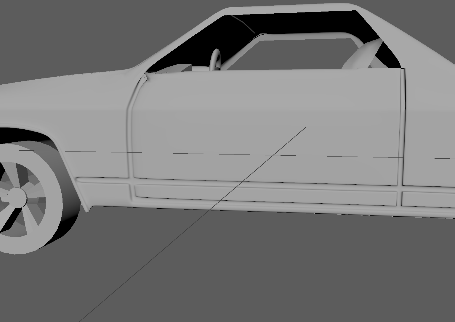
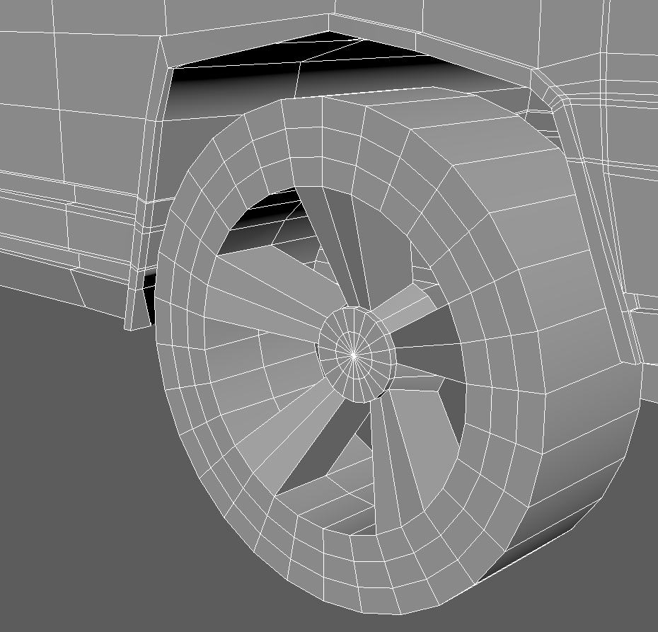
I would describe this part as the most difficult part of the car I had faced until then. I needed to accurately define the wheel wells for both the front and the back wheels of the car. While this may seem like a simple task, I found that simply adding edges by using the ‘multicut’ tool and the ‘insert edge loop’ exacerbated the topology of my model. So I needed to really visualize the model of the car and Added as few edge loops as possible to let me represent the wheel well curve in basic form. Had I used more edges here, I would have been able to give the curves some extra profile. But my cost to benefit ratio analysis of this told me otherwise. Notice that the wheel well curves in the front and the back aren’t exactly the same which is why it took much more effort to understand this not very easily perceivable difference in itself. I extrude the wheel well ridges to give it that extra thickness and beveled like appearance that can be seen in the toy model if looked at carefully.
I deleted faces to form the window on the side. To model the door dent, I added edge loops and moved around the vertices to match the door curve as seen in the model. I also did this to match the dent along the side frame that clears the ground. Notice how the frame isn’t exactly parallel to the ground. Once vertices were moved around to match the frame, I added extra edge loops around and extruded the faces that would define my curve inwards to give it a dent like appearance. In this step I found modeling the door frame and managing the vertices in an around the entire area to be a herculean task. I learned later that every extrusion even if not used, or pressed by mistake creates vertices and faces sometimes which ruins the topology of the model in a very pernicious way. This is because the extra faces, edges and vertices created are masked by other faces, edges and vertices which aren’t visible directly even if on wireframe mode. I also made of the split polygon tool to add more edges to faces whenever necessary
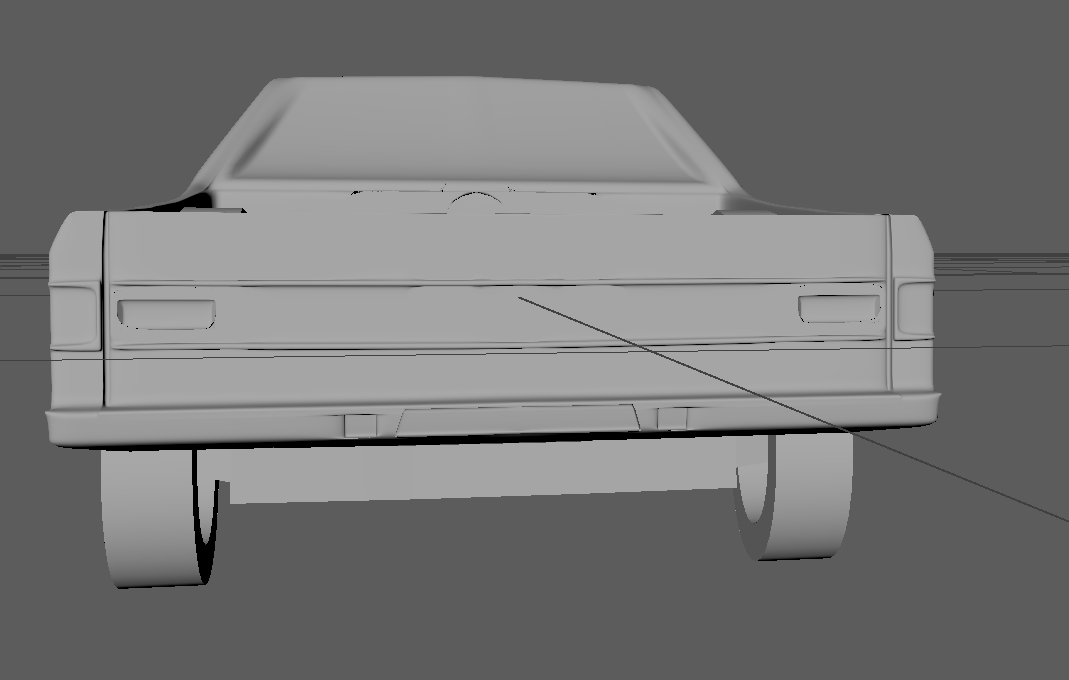
Modeling the back part of the car:
During this part of the modeling task, I added modeled the fuel tank in a way similar to that of how I modeled the door dents- extruding the faces of the shape inwards. Every time I did this, I checked in smooth mode and added extra edge loops to keep the necessary resolution. However at one point, it got to the point where I found it painful to look at the object in wireframe mode with so many vertices making me overwhelmed with modeling work for days. So I decided to clean up when I realized this problem much later during this phase however,I spent more time learning merging vertices, deleting extra edges and fixing topology after I created what seemed to me like a billion extra faces, edges and vertices somehow.
So I spent days just fixing whatever I could find that was redundant all throughout the car.
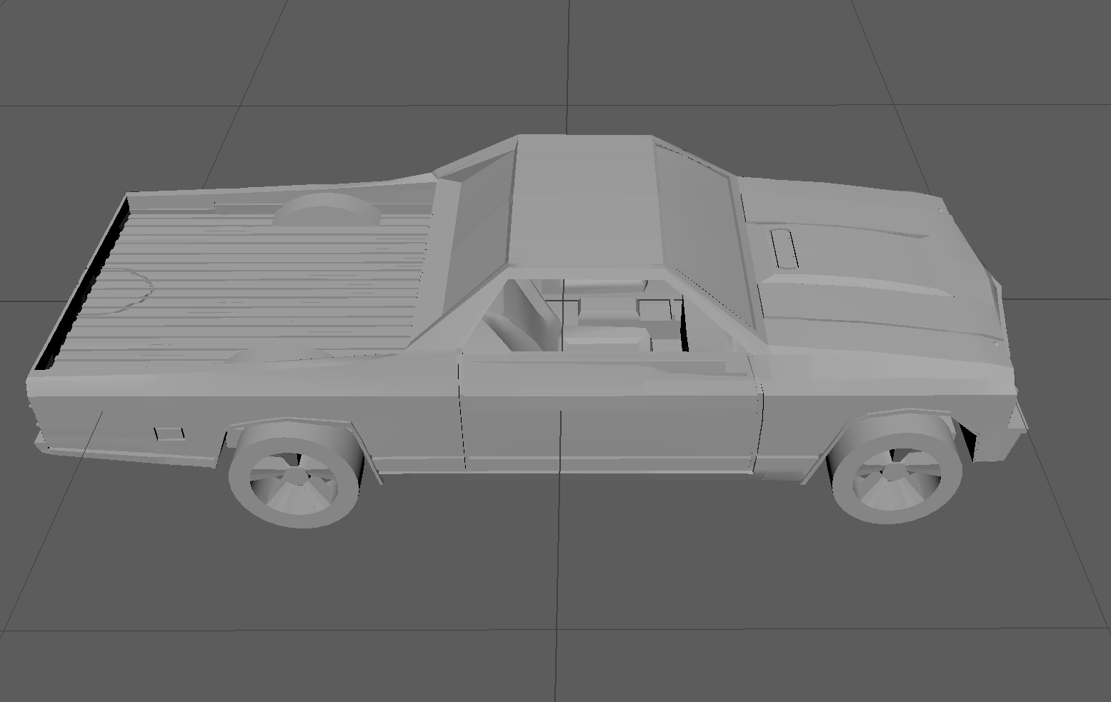
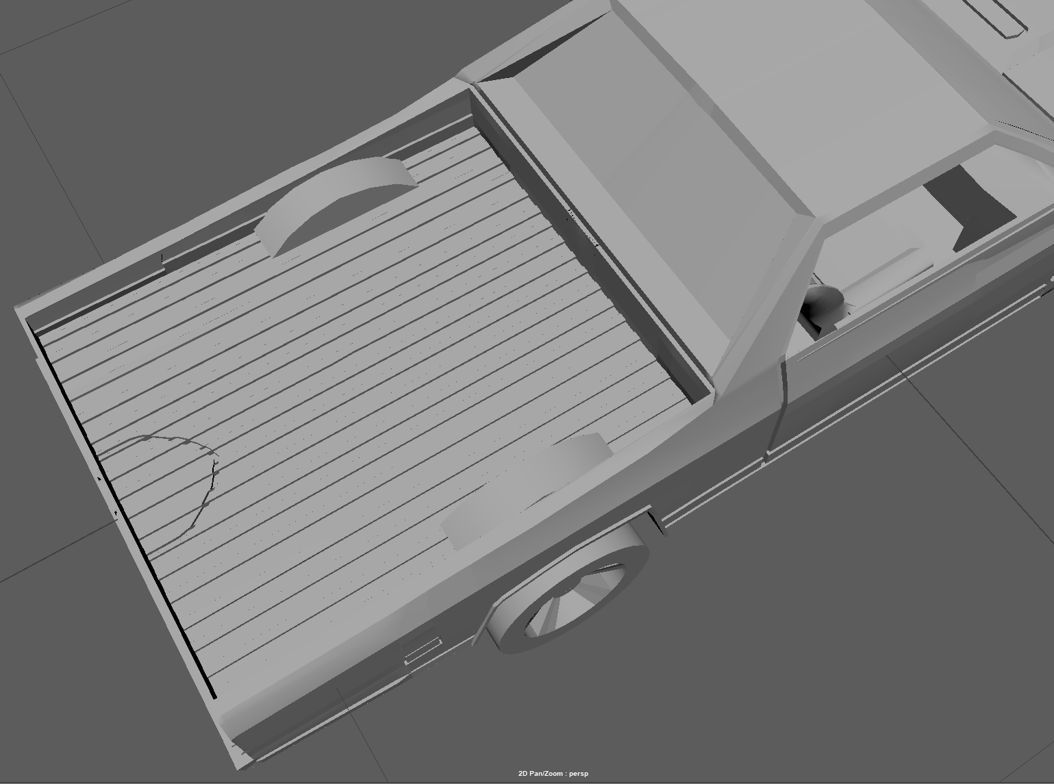
While modeling the back of the car, the trunk seemed to be one area where there were too many edge loops for comfort. Similarly It took me some time to understand that the door frame gradually tapered into the back frame of the car ultimately defining the top shape of the frame of the trunk. I moved around vertices to give the rail some thickness. I modeled the back view of the car in a way similar to the front. Extruding faces and moving faces, edges and vertices around to match that of the car. I also made sure that vertices in the same face were at the same plane by using the scale function when selecting multiple vertices. I learned to use the option of using only camera based selection to deal with problems like which would otherwise by default see through the vertices that are visible from the side view or front view and select them too. While modeling the trunk, I extruded the large face down added edge loops at the very to create the ridges. I also used the 'multicut' function to add extra vertices across for the arc in the trunks tail end. Whenever there was hole, I would use the ‘Append to polygon’ tool in the Menu to fill that gap. I also used the bridge and fill hole options when this didn’t work every now and then. I extruded the faces outwards to form the two ridges at the back with two dents creates using the edge loop tool and further extrusion. Similarly I created the rear lights on the tailgate by extruding the surfaces inwards.
Modeling the Wheels:
To model the wheels of the car I made use of a technique I learned from the 'Automotive modeling in Maya' tutorial. In this method, we use a cylinder and a pipe to model a wheel. The pipe would act as the outside tire that normally houses treads, grooves, etc. Meanwhile, the cylinder serves as the rim on the inner side from which spokes originate to the inner edge of the tire which is where the other would be. While doing this, we need to align both the pipe and the cylinder to be concentric with the pipe on the outside and the cylinder, inside. Thus the pipe would be larger than the cylinder. We must ensure that the number of subdivisions on the axes match between the pipe and the cylinder. The idea behind this is that the space between the axes in the smaller polygon (the cylinder in our case) would be lesser than the larger polygon (the pipe) even when we have the same number of sub-divisions. Thus the number of subdivisions on the pipe must be larger to avoid any rotational requirements. Following this, Simply combining faces will give the desired spokes. To connect the spokes, we can 'bridge' faces together in Edit Mesh menu. I added edge loops to tighten the spokes. I moved them to accurate position along the wheel well after this.
Modeling the base of the car:
To model the base of the car, I used a cube which spanned the length of the mod section of the vehicle. I extruded faces on the cubes front and back to match the length of the bases. After selecting the right faces, I extruded to form the axle of the car that connects wheel through the base. I also moved vertices of the extruding face to match the size of the rim of the wheel. Lastly i also made sure the cube was scaled high enough to account for the engine of the car right under the belly of the vehicle.
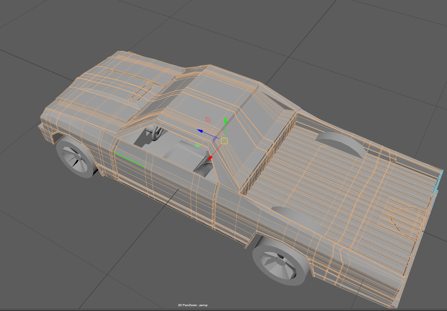
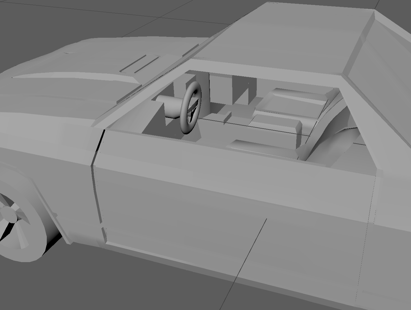
Modeling the interior of the car:
I used a narrow but deep cube to model the interior of the car which mainly deals with the dash board and the side rims and the console box. The dash board is a somewhat curved figure, so I moved around vertices after extruding faces gives it the appearance It has now. I extruded faces to let it house the steering wheel and gave a basic glove box like shape for the other passenger seat (shotgun position)
Modeling other minor objects:
Steering wheel:
I used a torus to model the steering wheel with a cube for the center where three buttons (cylinders) are placed. I created these polygons and moved around vertices and edges to model the wheel. I added three buttons. After I placed these tiny objects together, I combined their geometry going to the Mesh menu and selecting ‘combine’
Headlights
To model the Headlights, I used a cube Moved the vertices to form a point like base with a wider next frame. I extruded a face to keep the geometry in line with the car model. Next I created a polygon sphere and deleted half the sphere and add these to the top of the very short cube. After they placed accordingly, I merged these to form the headlight. I duplicated this to form another headlight for the left side.
Seat and console Box:
Modeling the seat required a cube and extrusion of the bottom face to form the base of the seat. To give it an angled appearance, I rotated the cube after doing so. I extruded the base of the seat’s face inwards to give it a bucket like appearance. I created flaps on the side in a similar fashion. For the console box, I simply used a cube and extrude a face for the cover.
Adding More detail:
This is the part where I spent most time creating the ridges in the trunk and adding the bumps in the front bumper. I made use of the ‘Chamfer Vertex’ tool to make a circular like appearance on the front bumper. This option takes a vertex and transforms it into a diamond of 4 vertices with each vertex connected to two others via two edges. So I used the multi cut option to add extra curve and extrude the face inside to give it a dent like appearance. I used a cylinder to model the bump on bonnet side similarly. I also used the 'mutli cut' tool to model the dent in the scoop of bonnet.
This is also the part where I added the arc on the trunk by moving vertices and extruding faces downwards. I spent a considerable amount of time looking for things to add and cleaning up by merging vertices, deleting unwanted faces and adding resolution through edge loops wherever necessary.
The final model looks somewhat better than my Initial Cube for one thing :P
That being said, I spent so much time on this assignment that I learned a lot of things I otherwise wouldn’t have
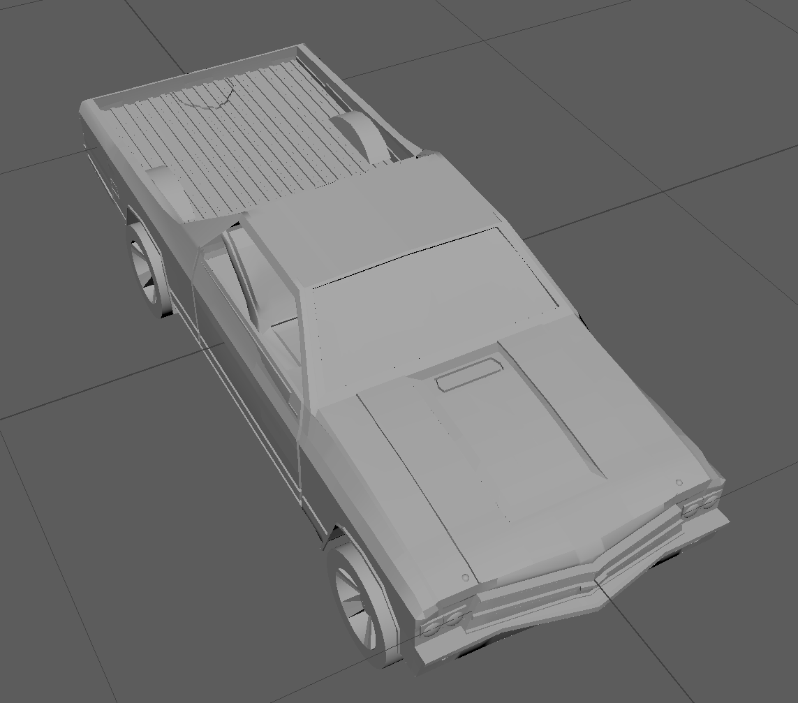
Initial Stage of Box Model provided below
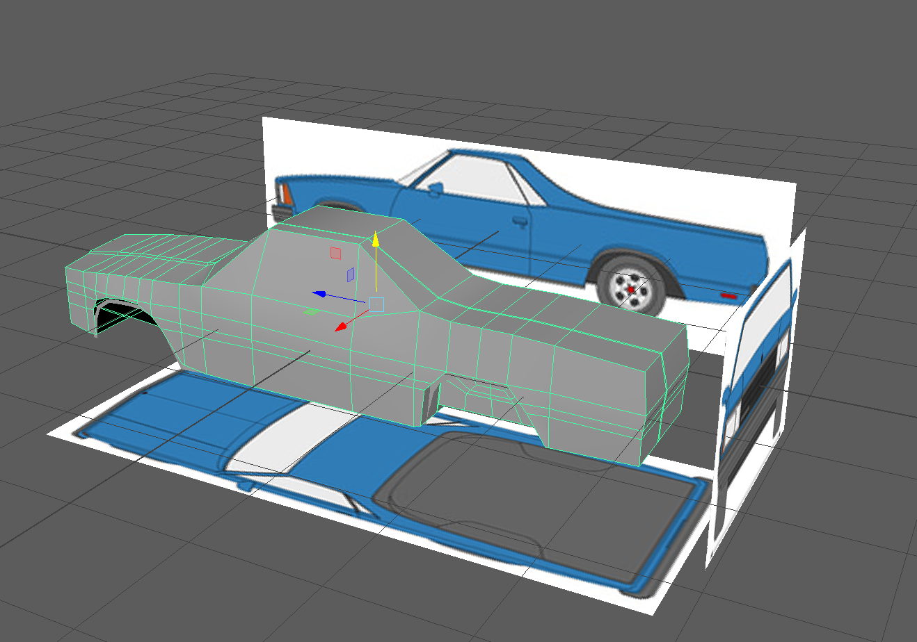
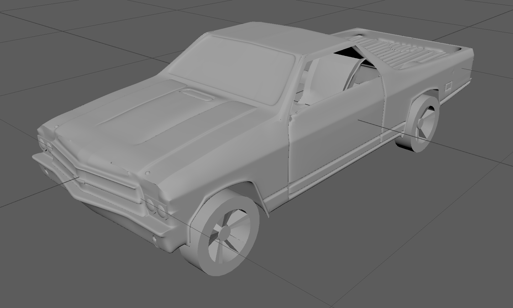
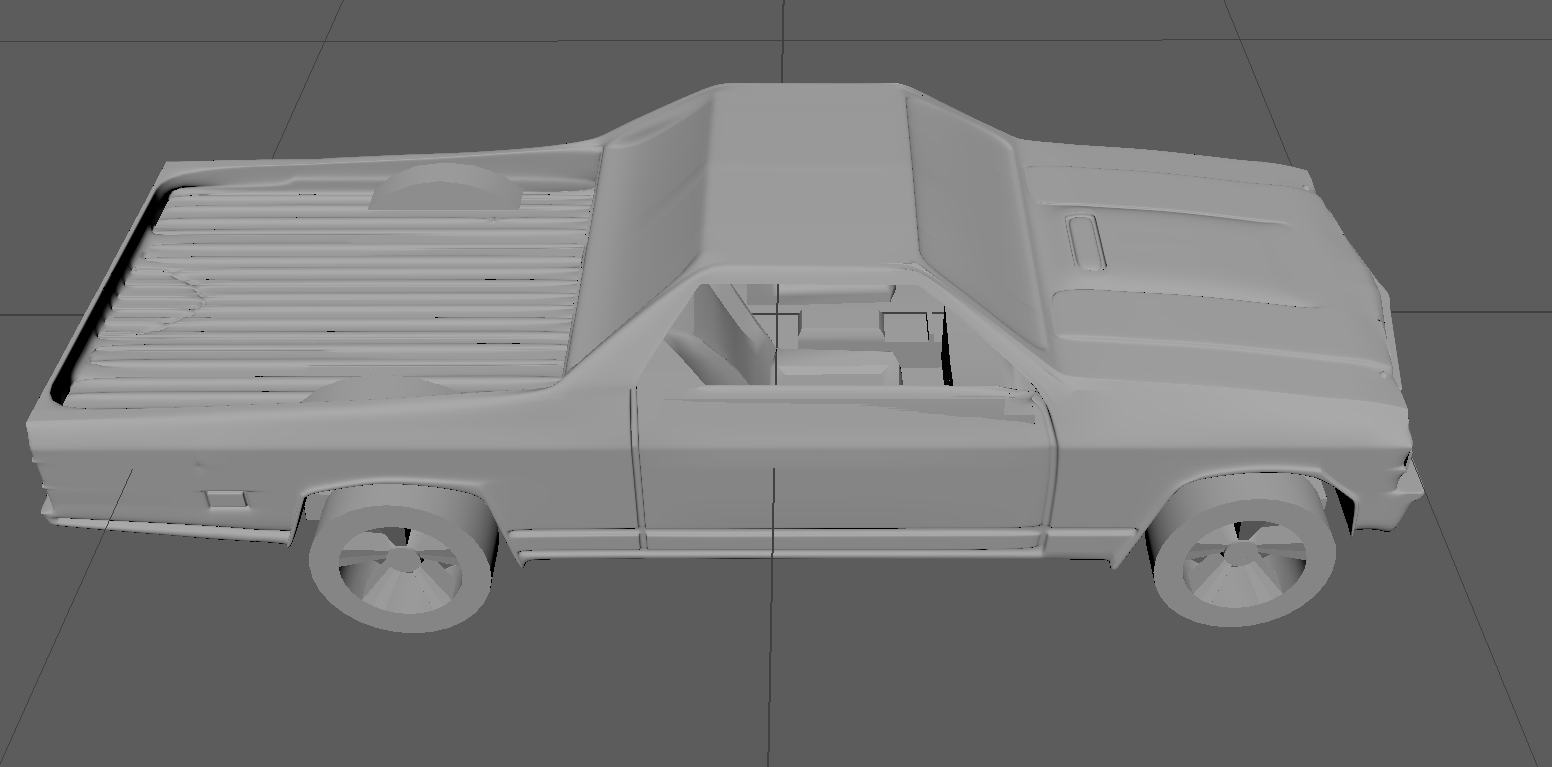
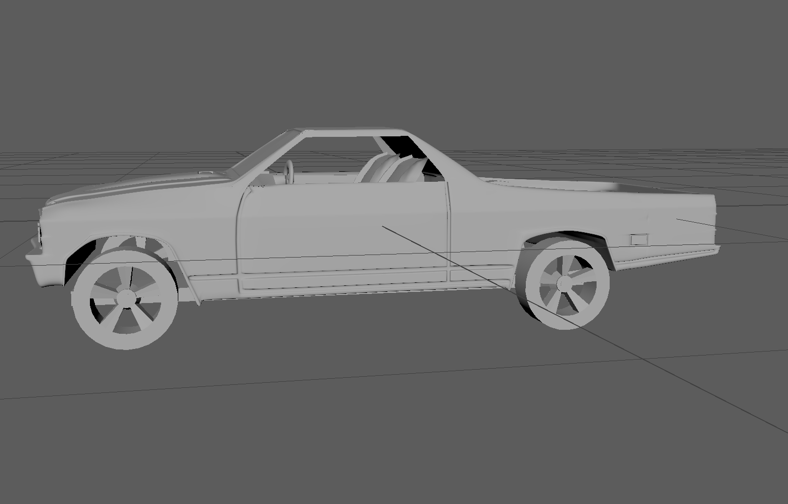
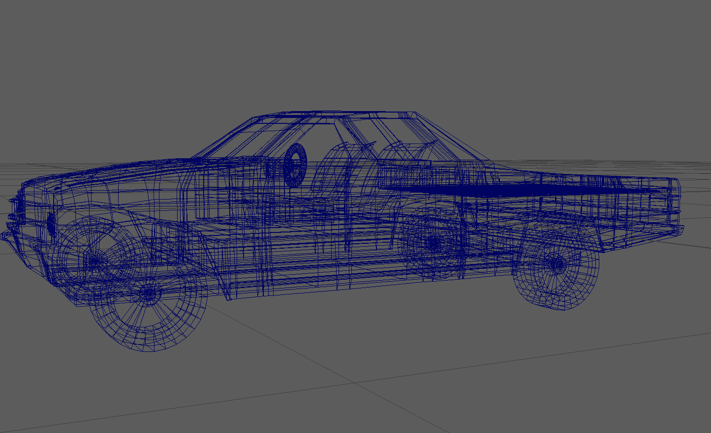
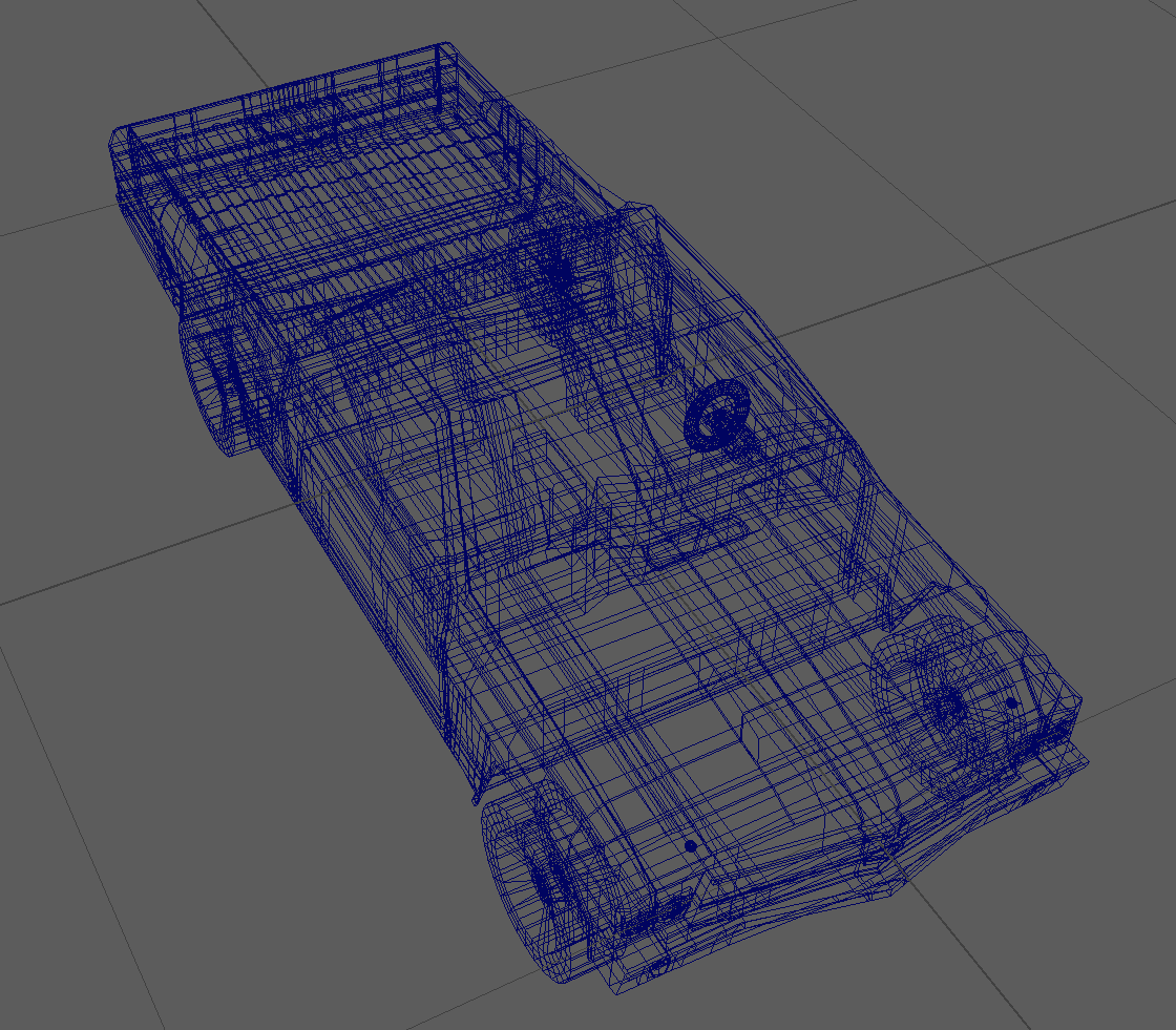
My Model Images provided below
Here is a link to the Maya File