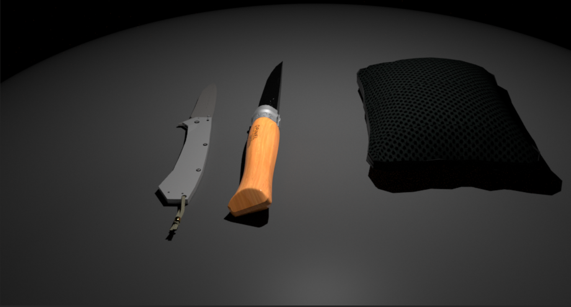
Modeling:
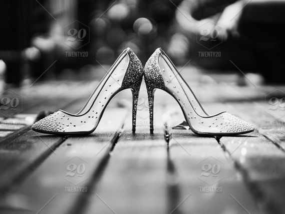
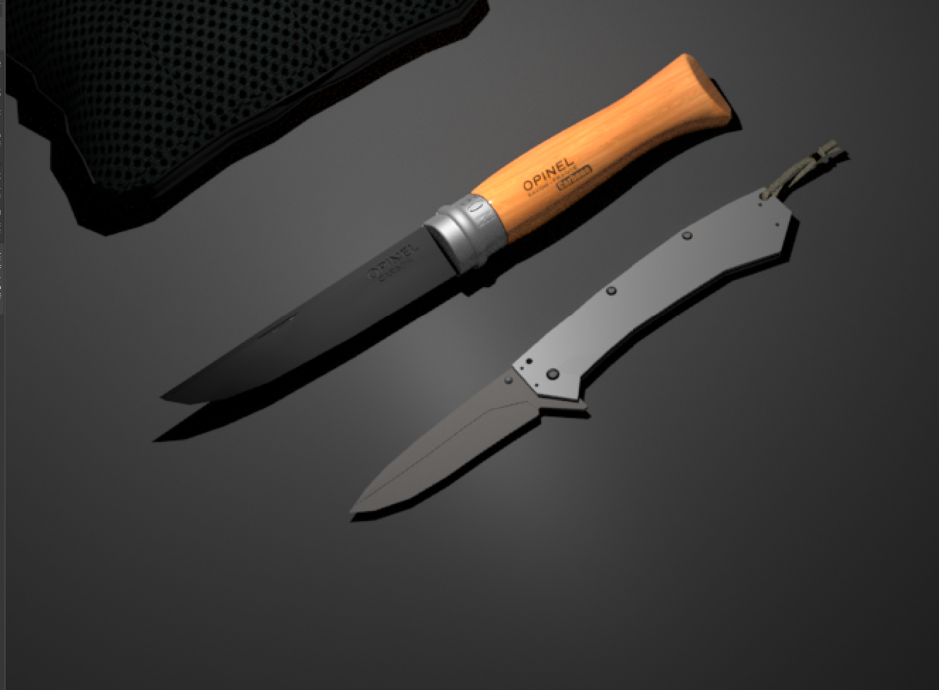
The modeling task required for this project was quite the ask. I was tasked with modeling two knives from the image above along with pouch. The Opinel knife was the most challenging modeling task not because of the complexity of the knife's shape and its structure, but rather due to the fact that the exact shape of the knife is very hard to tell from just an image. The kershaw knife was easier in comparison, but did take a while to model. For the base surface on which the knives sit, I created a plane.
Kershaw Knife:
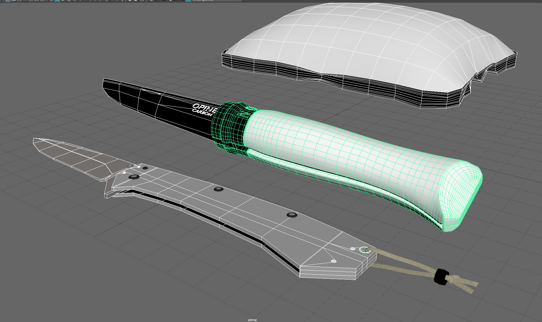
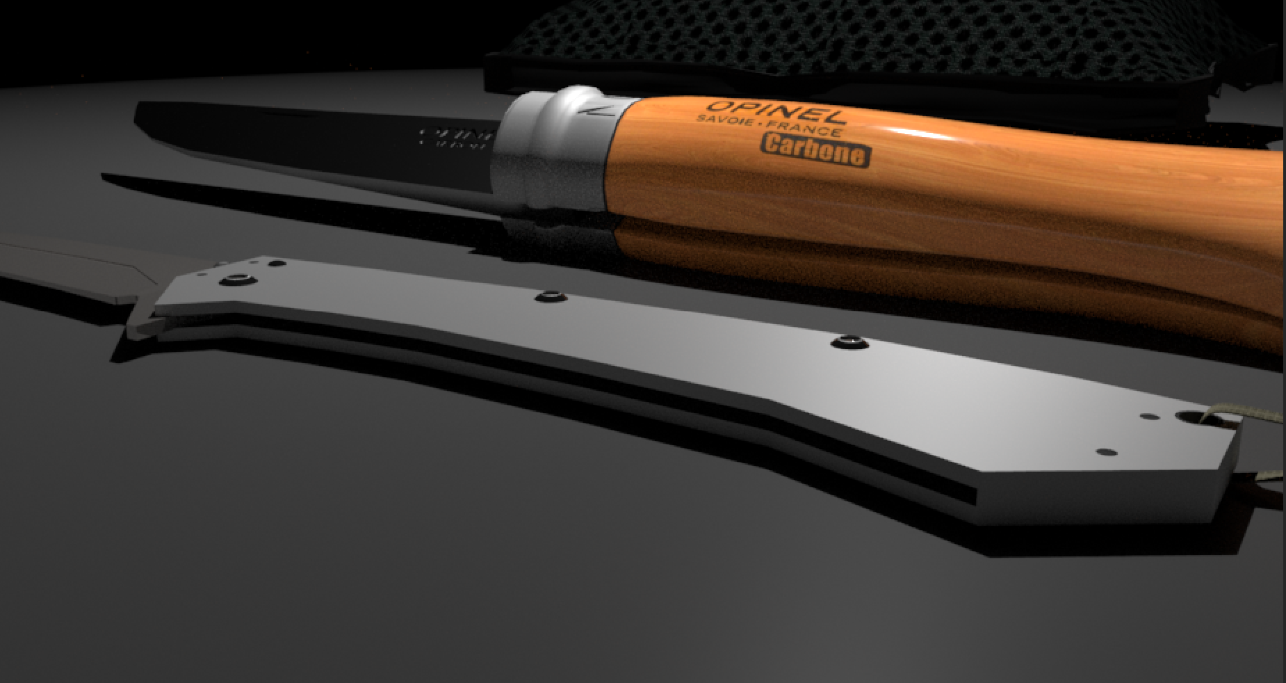
To model the Kershaw utility knife, I first started by using a cube for the handle of the knife. The size of the cube was taken to be roughly the size of a standard Kershaw knife. I added edge loops whenever I needed to define the geometry of the handle. This way we don't need to add unnecessary edges and complicate the geometry. I made sure to account for the slit space in the handle for the knife to fit in when folded. Adding the screws was relatively straightforward using spheres, cutting them in half and further scaling them.
The geometry of the handle had holes that go through the handle to support the use of lanyards and other string like materials. In order to make these holes in the handle, I made use of the Boolean difference operation. For this needed to create cylinders with a large enough radius that were the size of the holes. The idea behind the difference operation is that it allows us to create a 'difference' between the overlapping objects (the handle and the cylinder). So, I selected the handle first and then selected the cylinders which were placed in accordance with the reference image and then chose the difference operation under the Boolean option in the
in Mesh menu. But it is to be noted that applying this operation will affect the topology of the handle. I repeated this process for every single hole in the handle. For the blade of the knife, I used another cube and tapered the ends of the cube to give the blade a rather pointed look. I extruded faces inwards on the blade in order to give the knife some dimensionality as seen in the reference image.
in Mesh menu. But it is to be noted that applying this operation will affect the topology of the handle. I repeated this process for every single hole in the handle. For the blade of the knife, I used another cube and tapered the ends of the cube to give the blade a rather pointed look. I extruded faces inwards on the blade in order to give the knife some dimensionality as seen in the reference image.
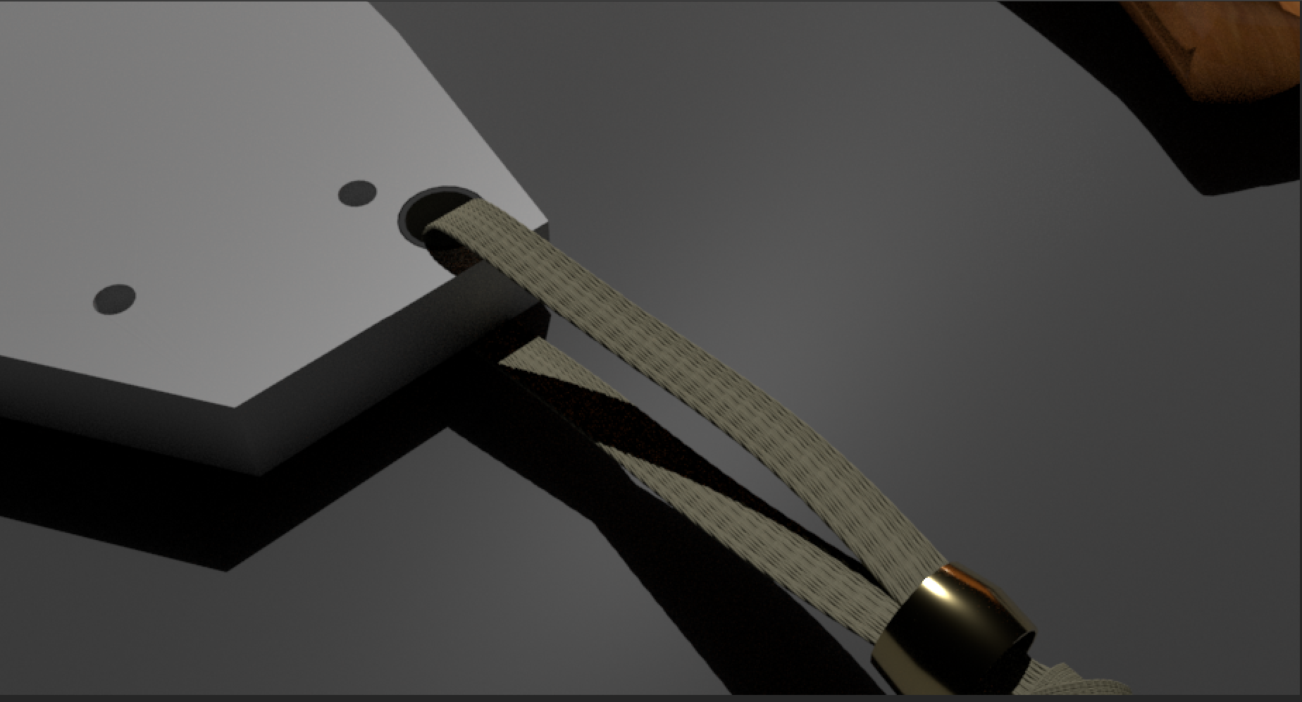
Another major challenge was modeling the lanyard attached to the handle of the knife. The method I used for the lanyard relied on the concept of extrusion along a curved surface. I hence created an EP curve that represented the curve and directionality of the lanyard in the reference material. Then I created 4 circular faces of equal radius, two on top of the other two. After combing their meshes to form a single object, I altered their scale to be small enough to represent threads of a lanyard. I placed them on the starting point of the curve, selected the four faces and then selected the curve and extruded them along the curve adding a thousand sub-divisons justifying the length of the lanyard. This represents one thread. I duplicated this thread placed it adjacent to the original thread and and repeated this about 6 times to create the lanyard. I realized that accurately having the shape of the curve of the lanyard according to the reference image made matters really difficult as the threads would go through each other rendering them unrealistic to even look at. So I kept the shape of the lanyard curve rather simple as seen in my model. Next I modeled the ring by creating a pipe and scaling the center edge along to give it that raised look. Modeling the knots in the lanyard was heavily time consuming. This required creating a somewhat circular EP curve (angled though) and creating a multitude of threads just as explained before. I created two threaded loops, scaled them accurately and placed them strategically to give the lanyard a knot like look.
Knife Pouch:
I pride myself on the way I handled this task of modeling. I first created a cube, scaled it appropriately by keeping the surface flat with very low thickness using a pouch-looking length to breadth ratio. Next I selected the FX view to create the pouch. I created a ncloth which also created a nucleus for this. I set an appropriate pressure of 0.5 and turned gravity off (set it to 0) for the ncloth cube. This would prevent it from falling due to the effect of gravity. Next I let the animation play in the bottom after making sure there was enough frames. I chose a suitable key-frame during the animation of the cube fluffing up like a pillow/cushion. I then duplicated this object and deleted all the type-by history to let me use that object as a modeled object on which I performed basic operations by translating, rotating and scaling, edges, faces, and vertices wherever appropriate. Next I beveled the top and lower edge faces and then extruded the faces to allow me create the rim like surface on the pouch. Then I applied the smooth view to gauge how well it resembled the reference image and made adjustments accordingly.
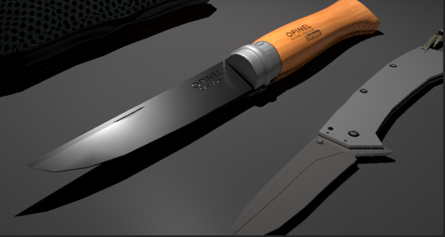
Opinel Knife:
To model this knife, the longest and hardest process was figuring out and really understanding the shape of the knife's handle. I stared modeling thinking I understood the shape, but after hours wasted based on incorrect assumptions and understanding, I found real Opinel knives online in different online retail stores. With the images of the knife posted on their websites, I was really able to understand the shape of these knives from the pictures from different viewpoints. Turns out that the knives fold in (never would have guessed this from just the image). I hence started modeling the handle based on the newly and more importantly, correctly understood geometry. I created one half of the handle by creating a cylinder and moving around vertices accordingly. After modeling the half, I mirrored it, and combined the meshes to create the handle. I did make sure to account for the knife slit which would be covered if the knife was folded in. I added extra edge loops and extruded the faces outward to create the protrusion visible in the reference image
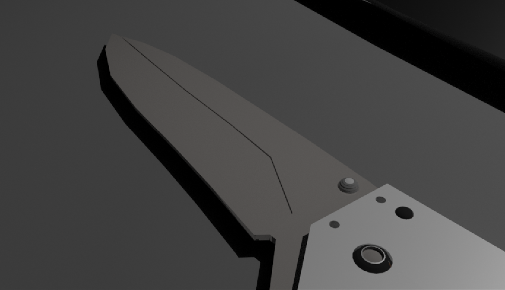
Modeling the blade of this knife was easier in comparison. I simply created a cube with sufficient number of axes along the width and moved around vertices in order to create the tapered look that a knife blade has. I used a cube with small thickness and the width was roughly the size of the blade of the knife. I also used to the multi cut tool to recreate the face that appears to be a depression on the knife's blade in the reference image. To create the depression, I extruded the face I created using the multicast inwards.
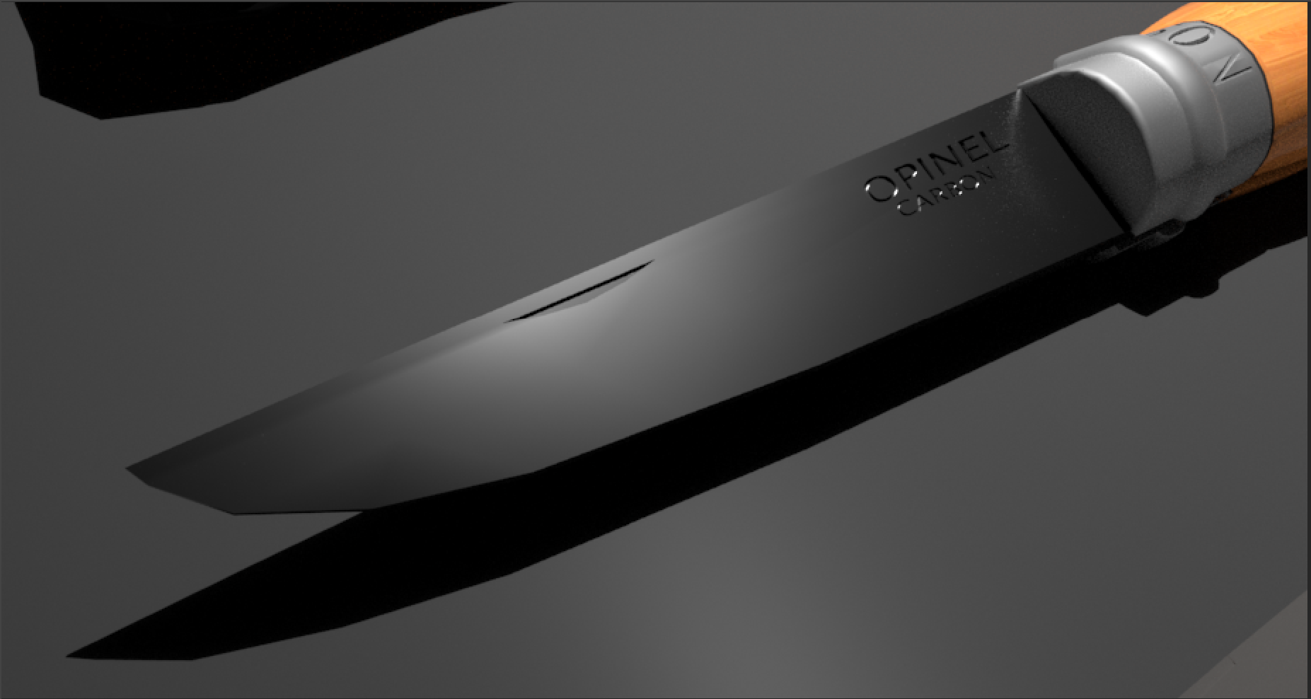
The text part of the knife's blade and rim was pretty straightforward. I created 3D type text with the words 'N 0 6' ( the carved/depressed text that can be seen on the rim ) , 'OPINEL' and 'CARBON' (the carved/depressed text on the blade of the knife). I placed these text types according to reference relative to my knife. To stencil the text into the blade and rim, I simply performed Boolean difference operations as the would created the difference between the selected meshes. Essentially, I used the blade and the rim and performed difference operations with these texts respectively. This created the engravings on the knife.
Lighting, Shading and Rendering:
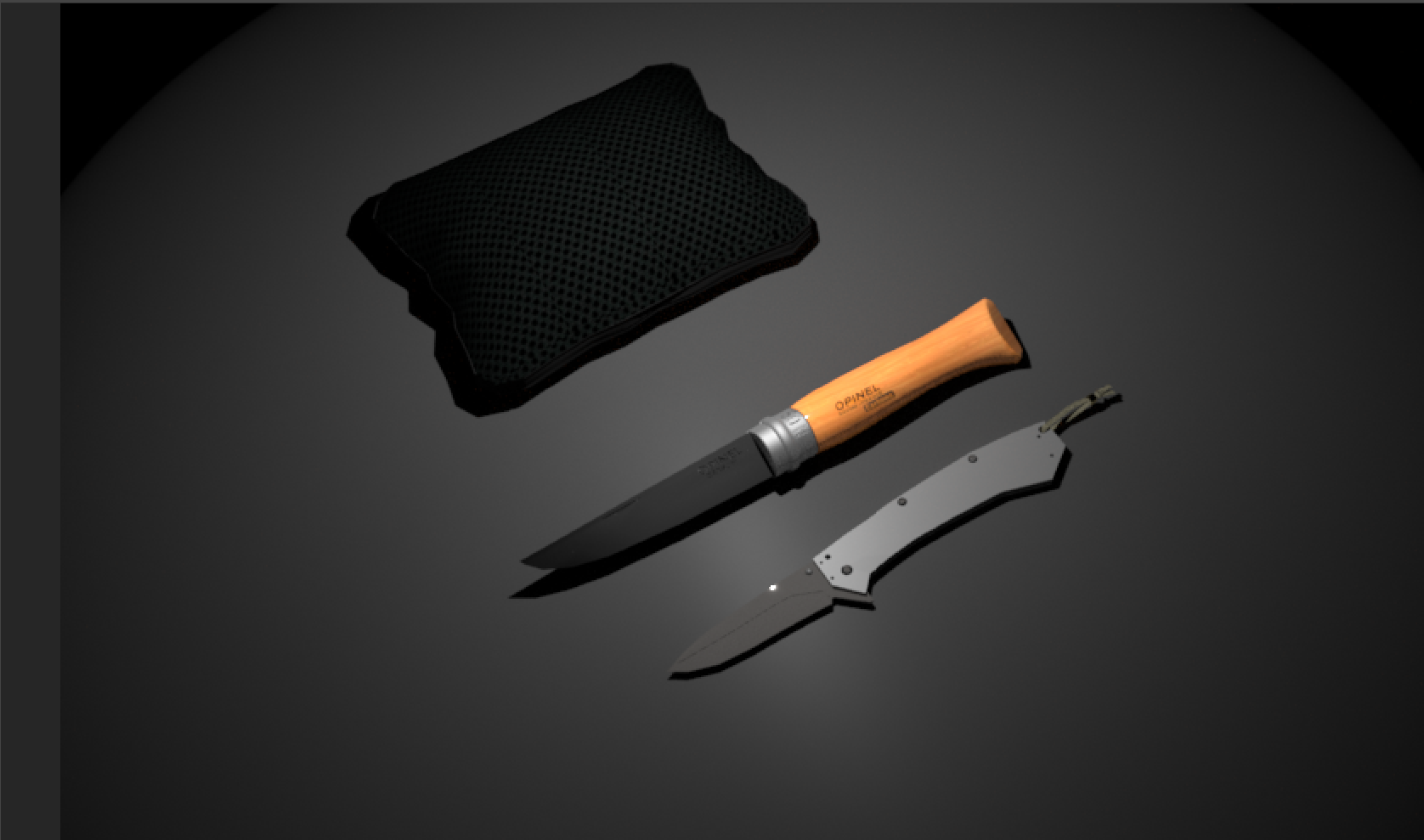
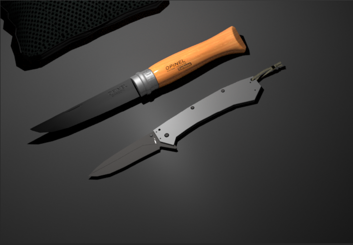
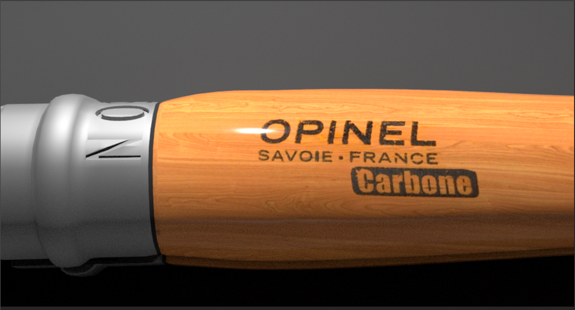
I created materials and shaded different faces of each model based on the reference image. For the surface of the Opinel utility knife, at first, I shaded the faces of the handle with a wooden texture I created by using the ArnoldStandard surface material I created. Much too close to the deadline, I realized that I needed to have text on the surface of the knife that reads 'OPINEL SAVOIE. FRANCE CARBONE' ! After doing a little bit of research, I figured out that using other software such as Substance Painter or Photoshop, I could seamlessly integrate the desired text into the texture by overlaying it. Sounds pretty easy right? Actually, the text that appears on the handle isn't just plain text but a logo too. So simply adding text on top wouldn't cut it. I hence had to download the logo and make the background transparent and overlay it on top of a wooden texture which was then added as a texture in Maya under a shader. After this I had to make adjustments to the faces in the UV editor to make sure the texture wasn't causing the text to be written horizontally and was appropriately sized. This took quite a lot of time to achieve. For the rim, I created an Arnold texture material and adjusted the properties like its base color, roughness, diffuse roughness, Anisotropy and other properties under the Emission, Coat, Subsurface, Sheen, Transmission and Specular sub menus. I had to make sure it reflected some light and appeared a tad bit shiny. For the blade of the Opinel knife, I created another material and played around with its shader properties to achieve the desired look.
Shading the Kershaw knife was relatively easier requiring the creation and fine tuning the properties of multiple Arnold standard surface materials that I created to reflect the right amount of light based on the reference image. I also shaded the screws with a chrome like material to give a rough, dark brushed look. After adding the lighting, it took quite some time to make sure the surface of the blade and the handle didn't reflect too much light. The pouch on the other hand required a mesh like look and a black velvety rim that runs around it. To shade the lanyard, I simply chose a cloth like texture from the Arnold materials and then applied the shader and then adjusted the shader properties to accurately represent the lanyard in the reference image (brownish gray look). The table surface was a smooth black-grey texture. I also used Substance Painter to create some noise on the table surface but for some reason, the texture file linking was broken, so I ended up using Maya to create them
At first I wasted time creating area lights, and directional lights when all that was required was a spot light and point source of light near the blade of the knife. I adjusted the intensity of the spotlight increasing to a high enough degree that it would illuminate the knives and the pouch to a decent degree. I also adjusted the cone angle and penumbra region values to make it look like the original.
For the rendering task, I made use of a couple of useful techniques to help render and dynamically compare shaders and lights. In one technique i learned how to create snapshots of certain render processes and compare them to see if certain adjustments were useful or not. This can be achieved with the Arnold render viewer. The other technique let me constantly compare the reference image to the rendered scene image by locking the view of the camera and setting the rendered view to represent the view from that camera. This was the angle of the scene was locked and judged from the main angle (the angle assumed in the reference image).
My main takeaways from this project are:
-> The modeling task in this project was way harder than it seemed at first.
-> Modeling something without understanding the exact geometry of the object proves to be a huge factor in determining how much time you spend modeling the object. The Opinel knife which looks rather easy to model from the reference image is actually difficult and abstract to model unless and otherwise you see the object from different angles.
-> Adding text on top of surfaces may require the use of other software.
-> Modeling threads requires careful precision using curves.
-> Using Boolean operations, we can easily perform useful operation on objects, but this comes at a cost- it affects the geometry of the shape. It hence may be useful to perform these operations at the right time, after dealing with other potential issues that could be affected by the geometry.
-> Stenciling on objects takes a lot of care and concentration.
-> We can easily create certain objects like pouches using the FX mode in Maya.
Here is a link to the Maya Folder.
Please download the files and make sure you've extracted the folder completely before opening the scene.
Please download the files and make sure you've extracted the folder completely before opening the scene.